8 before installing read system sensor s applications guide for duct smoke detectors hvag53 which provides information on detector spacing placement zoning wiring and special applications.
Duct smoke detector installation manual.
If the difference is greater than 0 15 volts there is enough air flow through the duct smoke detector for proper operation.
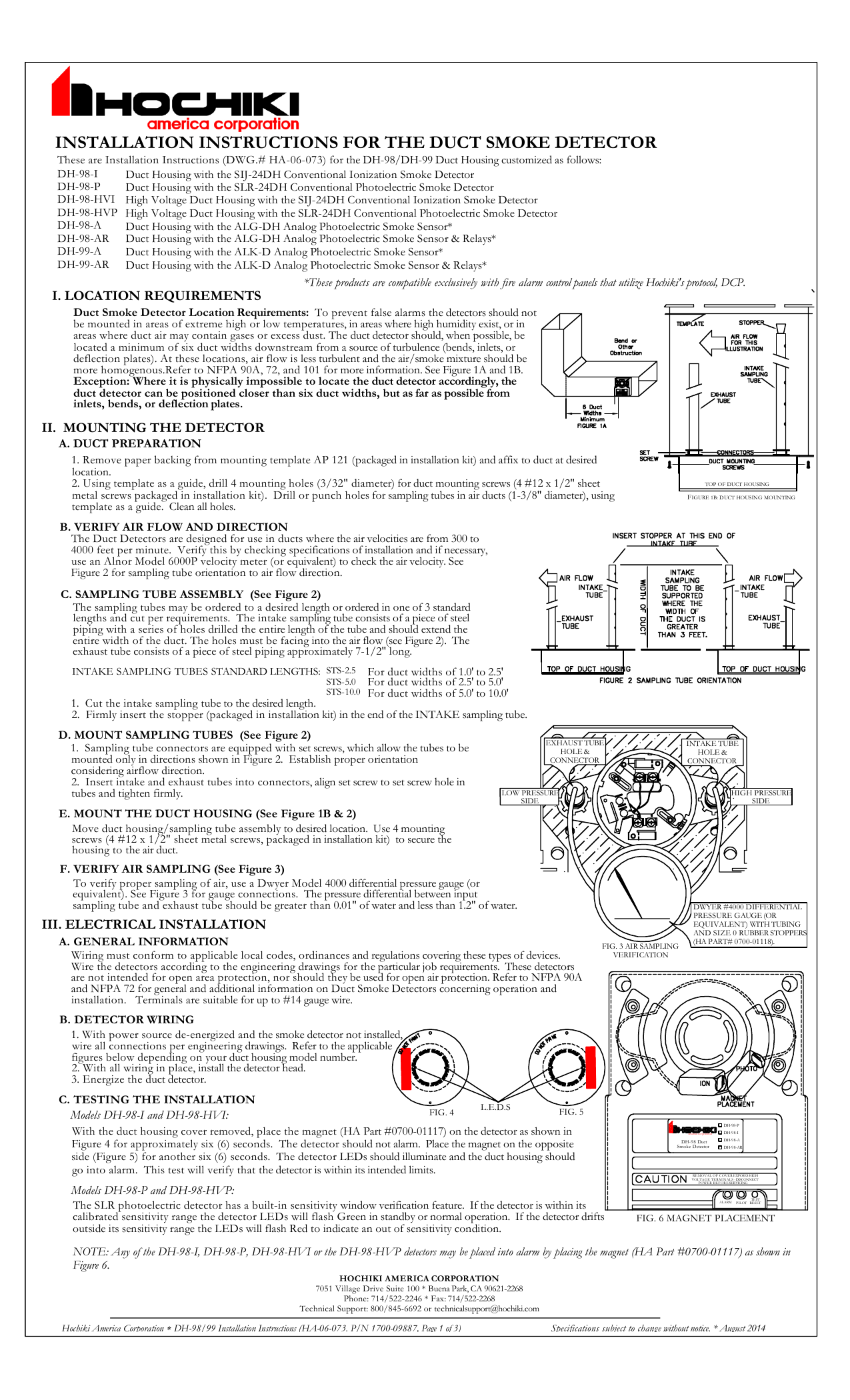
The ad2 series smoke duct detector should be greater than 0 01 inches of water and less than 1 2 inches of water.
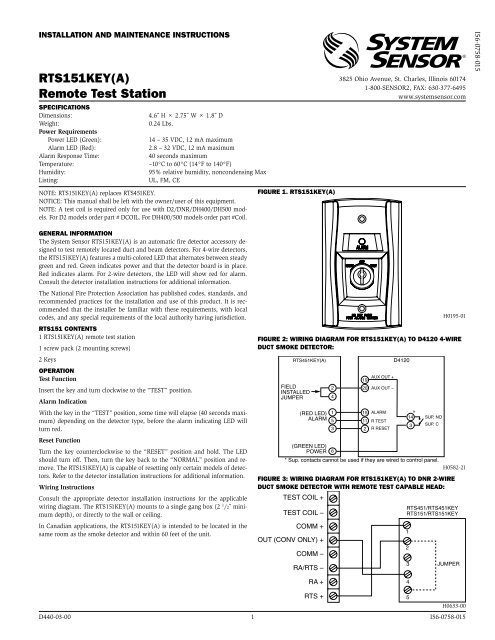
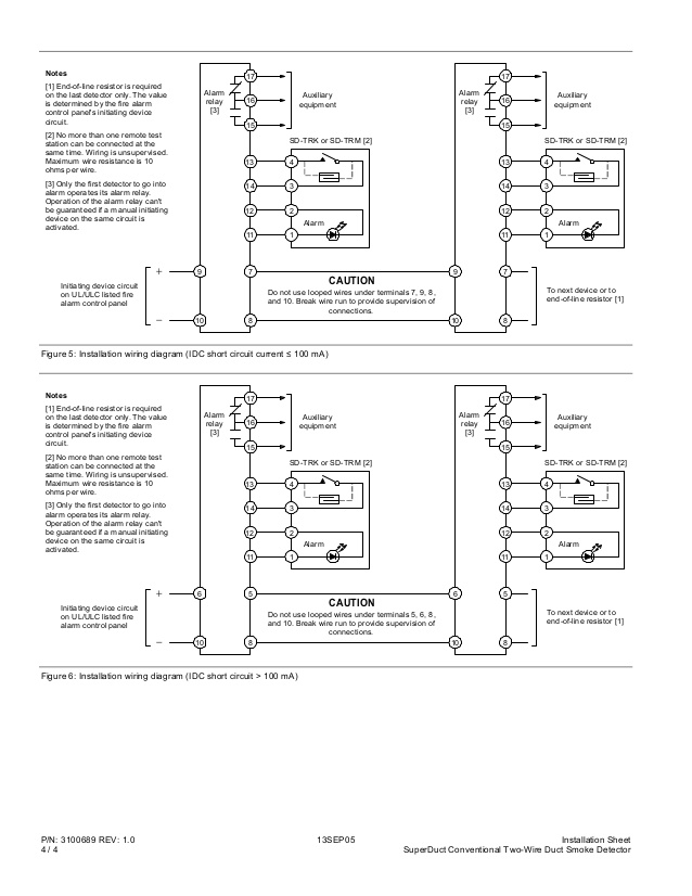
With power source de energized and the smoke detector not installed wire all connections per engineering drawings.
3 identify a code compliant location supply or return side or both for the installation of the duct unit that will permit easy access for viewing and serviceability.
Ing the performance application and installation of duct smoke detectors.
Failure to comply with these requirements may prevent the detector from activating when smoke is present in the air duct.
The duct smoke detector is designed for use in duct.
Energize the duct detector.
E pdd duct smoke detector installation sheet operation the duct smoke detector s primary purpose is to provide early warning of an impending fire and shut down the hvac unit in order to prevent smoke from circulating throughout the building.
With all wiring in place install the detector head.
Furthermore the detector must be operated within all electrical and environmental specifications listed in this manual and the sensor head installation manual.
To verify correct installation the pressure differential between the sampling high side and exhaust low side tubes should be measured using a magnehelic pressure gauge or equivalent.
Remove the end plug from the other sample tube.
4 when installing on the return side install duct units prior.
Read system sensor s applications guide for duct smoke detectors hvag53 which provides information on detector spacing placement zoning wiring and special applications.
Push the flared end over the sample tube you want to lengthen.
Duct smoke housings 4 wire 9 mounting en bosch security systems inc.
Measure and record the voltage drop across the 1000ω resistor measurement 2.
Remove the roll pin and set screw from one of the sample tubes.
Nfpa standards 72 and 90a should also be refer enced for detailed information.
Subtract the voltage recorded in measure ment 1 from the voltage recorded in measurement 2.
Instructions in this manual.
Nfpa standards 72 and 90a should also be referenced for detailed information.
Refer to the applicable figures below depending on your duct housing model number.


