Duct Detector Test Switch Wiring

System Sensor Duct Detector Wiring Diagram Awesome In 2020 Home Security Systems Alarm System Best Home Security

Zenith Motion Sensor Wiring Diagram Is One Example Of A Occupancy Motion Sensor Switch Wiring Diagram Bath Exhaust Fan Sensor Installation

New Hvac Wiring Diagram Test Questions Diagram Diagramsample Diagramtemplate Check More At Https Morningculture Co Hvac Wir Diagram Wire Chevy Trailblazer
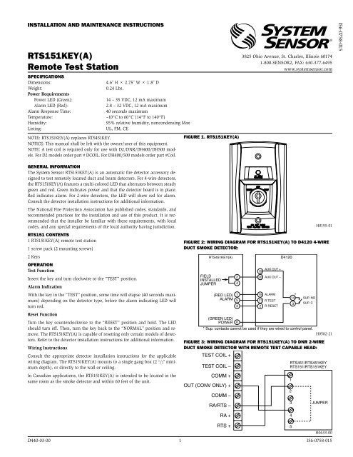
Rts151key A Remote Test Station System Sensor

Awesome Wiring Diagram Downlights Diagrams Digramssample Diagramimages Wiringdiagramsample Wiri Thermostat Wiring Thermostat Installation Backup Generator

Unique Basic Wiring Diagram For Car Lights Diagram Car Lights Car

The superducttwo wire duct smoke detector is ideally suited to applications where early indication of combustion is required within the confined space of ventilation ductwork.
Duct detector test switch wiring.

Hardwired Smoke Detector Wiring Diagram With Nm B 14 3 Cable Smoke Alarms Hardwired Smoke Detectors

Unique Light And Switch Diagram Diagram Wiringdiagram Diagramming Diagramm Visuals Visualisatio Alarm Systems For Home Smoke Alarms Home Security Systems

Fire Alarm Control Panel Wiring Diagram For Diagram Control Panel Paneling

Code Required Testing Of Fire Smoke And Combination Dampers Smoke Fire Life Fire
Source : pinterest.com
